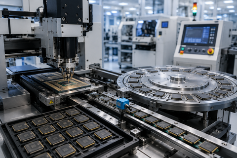
Industrial Gear Hobbing Machines Guide: Process and Tooling
Industrial gear hobbing machines are specialized gear-cutting machines that produce gear teeth by synchronously rotating a cutting tool called a hob and a workpiece.
This continuous machining process is widely used to manufacture spur gears, helical gears, splines, and other toothed components for automotive, industrial machinery, power transmission, and precision engineering applications.
Gear hobbing combines controlled rotary motion, precise workpiece positioning, and specialized cutting tools to produce repeatable tooth profiles. The choice of machine configuration, hob geometry, cutting conditions, and inspection methods determines the achievable accuracy, surface finish, and production efficiency.
Quick Facts About Industrial Gear Hobbing Machines
Feature | Description |
|---|---|
Primary function | Cutting gear teeth through synchronized rotary machining |
Main cutting tool | Gear hob |
Workpiece | Gear blank or compatible toothed component |
Core process | Continuous generating gear cutting |
Common gear types | Spur gears, helical gears, splines, and selected sprocket forms |
Machine configurations | Conventional, CNC-controlled, horizontal, and vertical |
Main tooling variables | Hob geometry, material, coating, and cutting parameters |
Important quality factors | Tooth profile, lead, pitch, runout, and surface finish |
Common industries | Automotive, aerospace, industrial machinery, and power transmission |
Finishing operations | Shaving, grinding, honing, or other processes when required |
What Are Industrial Gear Hobbing Machines?
An industrial gear hobbing machine cuts gear teeth using a rotating, multi-edged tool known as a hob. The hob and gear blank rotate in a coordinated relationship, allowing the cutting edges to progressively generate the required tooth spaces as the tool moves across the workpiece.
Unlike a process that cuts each tooth individually, hobbing generates multiple tooth spaces during a continuous machining cycle. This makes it suitable for repeat production, especially when manufacturing cylindrical gears in industrial quantities.
Modern gear hobbing machines may include CNC control, automatic tool changing, workpiece loading, in-process monitoring, and integrated inspection capabilities. Their configuration depends on the gear geometry, component dimensions, required accuracy, and production environment.
Why Gear Hobbing Matters in Industrial Manufacturing
Gears transmit motion and torque between rotating components. Their tooth geometry affects how loads are transferred, how smoothly the gears engage, and how much noise, vibration, and wear develop during operation.
Gear hobbing provides a repeatable method for manufacturing many external gear forms. It supports production planning because the cutting process can be configured around a defined workpiece, tool, and machining cycle.
Its principal industrial advantages include:
Continuous tooth generation rather than separate indexing for every tooth.
Repeatable production when machine setup and tooling are controlled.
Compatibility with a range of gear sizes and tooth geometries.
Potential integration with automated workpiece handling.
Flexible tooling choices for different materials and production needs.
Suitability for high-volume manufacturing as well as selected lower-volume applications.
Hobbing is not the ideal method for every gear. Internal gears, bevel gears, and certain specialized tooth forms usually require different machining processes.
Understanding the Gear Hobbing Concept
Simple Explanation
Imagine a cylindrical cutting tool with helical cutting edges rotating against a gear blank. As the blank rotates in synchronization with the hob, the cutting edges gradually form the gear teeth. The machine controls the relationship between the two rotations so that the resulting tooth spacing and geometry match the intended design.
The hob resembles a worm with cutting edges, but it is engineered specifically to generate gear teeth. Its geometry, mounting position, and relationship to the workpiece determine how material is removed.
The Generating Principle
Gear hobbing is a generating process. The tooth profile emerges from the coordinated motion of the hob and workpiece rather than being formed solely by the outline of a single cutting edge.
The required motion relationship depends on the hob's number of starts, the workpiece tooth count, and the intended gear geometry. Additional adjustments are necessary for helical gears because the tooth direction introduces an axial relationship between the cutting process and the workpiece.
This generating principle helps explain why hob selection, machine synchronization, alignment, and setup accuracy are essential to the finished gear.
How Industrial Gear Hobbing Machines Work
Step 1: Gear Blank Preparation
The process begins with a gear blank manufactured to the required dimensions. The blank may be produced through forging, casting, bar machining, or another suitable manufacturing route.
Before cutting, the blank's diameter, face width, bore, mounting surfaces, and material condition are checked against the component drawing. Accurate workholding and a suitable datum are essential because errors in the blank or its mounting can affect the final tooth geometry.
Step 2: Hob Selection and Mounting
The operator or manufacturing engineer selects a gear hob compatible with the required module or diametral pitch, pressure angle, tooth form, helix requirements, and workpiece material. The hob is mounted on the hob spindle using the specified arbor and clamping arrangement.
Tool condition, runout, mounting cleanliness, and alignment should be checked before machining. An incorrectly mounted or worn hob can introduce tooth-profile errors, vibration, poor surface finish, and premature tool failure.
Step 3: Machine Setup and Synchronization
The machine establishes the relationship between hob rotation and workpiece rotation. This relationship controls the number and spacing of the generated teeth.
For a single-start hob, one complete workpiece revolution corresponds to the generation of the number of teeth associated with the workpiece's tooth count. Multi-start hobs require a different rotational relationship because each additional start changes the generating action.
The machine also sets the hob's angular position, axial feed, cutting depth, and other parameters required by the gear design.
Step 4: Radial Infeed and Cutting Depth
The hob moves into the gear blank until the specified cutting depth is reached. The infeed strategy depends on the machine, tool geometry, workpiece dimensions, and cutting conditions.
The process must provide adequate tool engagement without creating excessive cutting forces or damaging the tool. Incorrect depth settings can produce tooth-depth errors and affect the gear's final geometry.
Step 5: Axial Feed and Tooth Generation
During cutting, the hob and workpiece rotate in synchronization while the tool advances across the gear face. The successive cutting edges progressively generate the tooth spaces.
Axial feed, cutting speed, hob geometry, and workpiece material influence cycle time, surface finish, tool wear, and dimensional consistency. The appropriate values depend on the machine and application rather than a universal setting.
Step 6: Tool Retraction and Part Removal
After the required tooth spaces have been generated, the tool is withdrawn and the workpiece is removed or transferred to the next operation. Automated machines may coordinate loading, clamping, machining, and unloading to reduce manual handling.
The finished gear may then undergo deburring, cleaning, heat treatment, or tooth finishing, depending on its material and final specification.
Step 7: Inspection and Process Adjustment
The machined gear is checked against its drawing and quality requirements. Inspection may include tooth thickness, profile deviation, lead deviation, pitch variation, runout, and surface condition.
If deviations occur, the manufacturing team investigates the likely cause before changing offsets, tooling, or machining parameters. Adjustments should be based on measured results rather than trial-and-error changes that could introduce additional errors.
Gear Hobbing Workflow Table
Process Stage | Main Activity | Quality Check |
|---|---|---|
Blank preparation | Prepare and verify the gear blank | Dimensions and mounting datums |
Tool selection | Choose the appropriate hob | Geometry, material, and tool condition |
Setup | Mount hob and workpiece | Alignment and runout |
Synchronization | Establish rotational relationship | Tooth count and generating settings |
Infeed | Set the cutting depth | Tooth-depth requirements |
Cutting | Generate teeth through synchronized motion | Cutting stability and surface condition |
Unloading | Remove the machined part | Handling and part identification |
Inspection | Measure the finished gear | Drawing tolerances and gear accuracy |
Finishing | Perform additional operations when required | Final geometry and surface quality |
Industrial Gear Hobbing Machine Architecture and Construction
Machine Bed and Structural Frame
The bed supports the machine's major assemblies and resists the forces generated during cutting. Structural rigidity helps limit vibration and relative movement between the hob and workpiece.
Machine construction, foundation conditions, thermal behavior, and maintenance condition all influence machining stability. Heavy-duty industrial gear hobbing machines are designed around the dimensions and loads of the components they are intended to process.
Hob Spindle and Drive System
The hob spindle holds and rotates the cutting tool. Its drive system must provide the speed range, torque, and motion control required by the cutting operation.
Spindle runout, bearing condition, tool clamping, and thermal stability influence machining consistency. CNC machines coordinate spindle operation with the workpiece axis and other controlled movements.
Workpiece Spindle and Fixture
The workpiece spindle holds the gear blank and rotates it in a controlled relationship with the hob. The fixture or workholding arrangement must prevent movement while maintaining correct alignment.
Clamping methods depend on the part's shape, bore, face width, and production requirements. Poor workholding can produce runout, dimensional variation, vibration, or part damage.
Feed and Positioning Axes
Feed axes control the relative movement between the hob and workpiece. Depending on the machine configuration, these may support axial feed, radial infeed, swiveling, and other movements required for the gear geometry.
The precision and repeatability of these axes affect the generated tooth form. Proper calibration and maintenance are necessary to preserve the intended motion relationship.
CNC Control and Programming
A CNC gear hobbing machine coordinates the spindle rotations, feed movements, tool positioning, and machining sequence. Programs are developed from the gear geometry and the machine's capabilities.
CNC control can support repeatable setups, stored machining programs, automated sequencing, and diagnostic functions. However, programming cannot compensate for an unsuitable hob, poor workholding, incorrect setup data, or a machine that is out of calibration.
Coolant and Chip Management
Coolant or cutting fluid may be used to manage heat, lubrication, and chip evacuation. Some machines and tool combinations support dry cutting or minimum-quantity lubrication, provided the process is engineered for those conditions.
Chip conveyors, filtration arrangements, guards, and enclosures help manage the by-products of machining. Their design must account for chip size, coolant characteristics, and the workpiece material.
Main Components of Industrial Gear Hobbing Machines
Component | Primary Function | Important Consideration |
|---|---|---|
Machine bed | Supports machine assemblies | Rigidity and stability |
Hob spindle | Rotates the cutting tool | Runout and speed control |
Workpiece spindle | Rotates the gear blank | Synchronization and accuracy |
Hob arbor and clamping | Secures the hob | Compatibility and mounting precision |
Feed axes | Control tool movement | Positioning accuracy |
CNC controller | Coordinates machining movements | Programming and synchronization |
Workholding fixture | Locates and clamps the blank | Repeatability and rigidity |
Coolant system | Manages cutting conditions where applicable | Fluid condition and delivery |
Chip management equipment | Removes machining debris | Reliable evacuation |
Inspection equipment | Verifies gear quality | Measurement capability and calibration |
Types of Industrial Gear Hobbing Machines
Gear hobbing machines can be classified by workpiece orientation, level of automation, machine configuration, and intended production task. These classifications describe different design characteristics and are not necessarily mutually exclusive. For example, a CNC machine can also be a vertical gear hobbing machine.
Conventional Mechanical Gear Hobbing Machines
Conventional machines use mechanical drive and control arrangements to coordinate the cutting process. Their capabilities depend on the machine's design, available change gears or control mechanisms, and supported gear geometry.
Advantages:
Established machining principles.
Suitable for compatible recurring production tasks.
Can remain useful where the required gear range matches the machine.
Limitations:
Setup changes may require more manual adjustment.
Complex machining sequences may be less flexible.
Precision depends on mechanical condition and setup quality.
CNC Gear Hobbing Machines
CNC gear hobbing machines coordinate the hob, workpiece, and feed axes through programmed control. They are used for repeatable production of a range of compatible gear geometries.
Advantages:
Programmable machining sequences.
Repeatable setup and axis coordination.
Potential integration with automatic loading and inspection.
Limitations:
Require suitable programming and setup expertise.
Depend on control-system compatibility and maintenance.
Initial integration and process validation can be demanding.
Vertical Gear Hobbing Machines
Vertical machines generally arrange the workpiece spindle vertically. This configuration can support convenient loading and unloading, particularly for selected workpiece geometries and production layouts.
Advantages:
Can simplify handling for compatible components.
May support compact production-cell arrangements.
Available with different automation configurations.
Limitations:
Suitability depends on workpiece size and geometry.
Handling equipment must match the machine layout.
Not every part benefits from vertical orientation.
Horizontal Gear Hobbing Machines
Horizontal machines arrange the workpiece spindle horizontally. They are used for many cylindrical gear applications and can accommodate different workholding and loading arrangements.
Advantages:
Suitable for many shaft-mounted gear components.
Can accommodate a range of workpiece configurations.
May integrate effectively with established machining lines.
Limitations:
Part support and chip management require careful planning.
Long or slender workpieces may need additional support.
Capacity varies substantially by machine design.
High-Production Automated Hobbing Systems
Automated gear hobbing systems combine the machine with equipment such as loaders, unloaders, part conveyors, gauging stations, and production controls. They are intended to reduce manual handling and improve process consistency across repeated operations.
Advantages:
Reduced manual handling between cycles.
Potential for consistent, repeatable production.
Better coordination with upstream and downstream operations.
Limitations:
Automation adds integration and maintenance requirements.
Production interruptions may affect connected equipment.
Changeovers require suitable tooling and process planning.
Gear Hobbing Machine Type Comparison
Machine Type | Main Characteristic | Suitable Use Case | Key Consideration |
|---|---|---|---|
Conventional mechanical | Mechanically coordinated operation | Established, compatible production tasks | Setup flexibility |
CNC | Programmed axis coordination | Varied gear geometries and repeat production | Programming and integration |
Vertical | Vertically oriented workpiece spindle | Compatible workpieces and handling layouts | Loading and workholding |
Horizontal | Horizontally oriented workpiece spindle | Many cylindrical gears and shaft components | Part support and chip handling |
Automated system | Integrated loading and process handling | Repetitive production sequences | System integration and changeover |
Gear Hobbing Tooling: Hobs, Materials, and Coatings
Tooling selection is central to gear hobbing performance. The hob must match the intended tooth geometry and workpiece material while withstanding the cutting forces and thermal conditions of the process.
Gear Hob Geometry
A gear hob is a cylindrical cutting tool with helical flutes and cutting edges arranged to generate the required tooth form. Its specifications may include module or diametral pitch, pressure angle, number of starts, helix direction, outside diameter, and overall tool geometry.
The correct geometry depends on the gear drawing and the machine setup. A hob intended for one tooth system should not be assumed suitable for another simply because the workpiece diameter is similar.
High-Speed Steel Hobs
High-speed steel, or HSS, is widely used for gear hobs because it combines hardness with toughness and can be resharpened when the tool design permits. Powder-metallurgy HSS grades may provide enhanced properties for demanding cutting conditions.
HSS hobs can suit a broad range of production environments. Their practical performance depends on the grade, heat treatment, coating, cutting parameters, and workpiece material.
Carbide Gear Hobs
Carbide tooling can support higher cutting speeds and productive machining under suitable conditions. Its hardness and hot-hardness characteristics are advantageous in applications where thermal loading is important.
However, carbide is generally less tolerant of certain impact and vibration conditions than tougher HSS tooling. Machine rigidity, workholding, tool design, and cutting strategy must therefore be considered before selecting a carbide hob.
Coated Gear Hobs
Surface coatings can improve resistance to wear and heat under compatible cutting conditions. Common coating families include titanium nitride and titanium-aluminium-nitride-based coatings.
A coating does not automatically improve every process. Performance depends on the substrate, coating properties, workpiece material, lubrication strategy, and cutting conditions. Regrinding and recoating must also follow a suitable tooling process.
Hob Starts and Cutting Strategy
The number of starts on a hob affects the relationship between tool rotation and workpiece rotation. Multi-start hobs can improve productivity in compatible applications, while a single-start hob may be preferred where the required generating conditions favor it.
Tool selection should consider the required tooth quality, cycle time, machine capability, and tool life together rather than optimizing only one variable.
Gear Hobbing Tooling Comparison
Tooling Option | Main Strength | Main Consideration | Typical Selection Context |
|---|---|---|---|
HSS hob | Toughness and resharpening potential | Cutting speed and thermal loading | General gear production |
Powder-metallurgy HSS hob | Enhanced material properties for demanding conditions | Grade and application compatibility | More demanding cutting conditions |
Carbide hob | High hot hardness and productive cutting potential | Rigidity and sensitivity to impact | Suitable high-production processes |
Coated hob | Improved wear resistance under compatible conditions | Coating and substrate compatibility | Applications requiring improved tool life |
Materials and Workpiece Requirements for Gear Hobbing
Gear Blank Materials
Industrial gear hobbing machines process a range of materials, provided the machine, hob, and cutting conditions are appropriate.
Low-carbon and alloy steels: Common in transmission components, industrial gearboxes, and power transmission equipment.
Cast iron: Used in selected industrial drive and machinery applications.
Stainless steels: Require suitable tooling and cutting conditions because machinability varies by grade.
Nonferrous metals: Certain brass, bronze, and aluminium alloys can be hobbed with compatible tooling.
Engineering plastics: Selected plastics can be machined when the tool geometry and cutting conditions are suited to the material.
The material's hardness, strength, abrasiveness, and heat-treatment condition influence cutting forces, tool wear, chip formation, and achievable surface finish.
Gear Geometry Requirements
Before selecting a CNC gear hobbing machine or gear cutting tool, establish the essential gear parameters:
Module or diametral pitch.
Number of teeth.
Pressure angle and tooth system.
Gear outside diameter and face width.
Spur or helical tooth configuration.
Helix angle and direction where applicable.
Required tooth profile and lead modifications.
Bore, shaft, and workholding dimensions.
Required gear accuracy and surface finish.
These details determine whether the selected machine and hob can generate the intended geometry within the specified tolerances.
Cutting Fluid and Chip Evacuation
Cutting fluid may provide lubrication, cooling, and chip evacuation. Its use depends on the workpiece, tool material, cutting conditions, and machine design.
Dry hobbing and minimum-quantity lubrication are possible in appropriately engineered processes. Neither should be adopted without checking tool compatibility, thermal behavior, chip evacuation, and the manufacturer's operating recommendations.
Gear Hobbing vs. Gear Shaping, Milling, Skiving, and Grinding
Gear manufacturing involves several distinct processes. Hobbing is particularly suited to generating external cylindrical gears, while other methods may be preferable for internal teeth, restricted access, specialized geometries, or high-accuracy finishing.
Process | Working Principle | Main Strength | Typical Limitation |
|---|---|---|---|
Gear hobbing | Synchronized rotating hob and workpiece | Continuous generation of external teeth | Not suitable for most internal gears |
Gear shaping | Reciprocating cutter synchronized with the workpiece | Can produce internal and external gears | Reciprocating motion affects productivity |
Gear milling | Form cutter removes material from tooth spaces | Flexible for selected parts and small production runs | Usually requires separate indexing between teeth |
Power skiving | Synchronized rotating cutter and workpiece with crossed axes | Efficient production of suitable internal and external gear forms | Requires specialized machine control and tooling |
Gear grinding | Abrasive wheel removes material from tooth flanks | Precision finishing, including hardened gears | Adds equipment, process, and finishing requirements |
When to Choose Gear Hobbing
Hobbing is a strong candidate when the component is an external cylindrical gear and the required tooth geometry is compatible with the hob and machine. It is particularly useful when a consistent cutting cycle and repeat production are important.
When Gear Shaping Is More Suitable
Gear shaping can produce internal gears and external gears that are difficult to access with a hob, including certain components located near shoulders. Its reciprocating cutter motion makes it a useful alternative when workpiece geometry limits hobbing.
When Power Skiving Is More Suitable
Power skiving uses synchronized rotating tools and workpieces with crossed axes. It can produce internal gears and other compatible geometries, often with productive cycle times, but requires suitable tooling, machine rigidity, and synchronization.
When Gear Grinding Is Required
Gear grinding is generally a finishing process rather than a direct replacement for initial tooth generation. It is used when the specified accuracy, surface condition, or post-heat-treatment correction cannot be achieved through the preceding manufacturing steps alone.
Benefits and Advantages of Industrial Gear Hobbing Machines
Production Efficiency
The continuous generating action allows multiple tooth spaces to be formed during a coordinated cutting cycle. This can reduce the repeated positioning required by form milling and support consistent output in recurring manufacturing operations.
Repeatability
When the machine, workholding, hob, and cutting parameters are properly controlled, hobbing can produce repeatable gear geometry across a production run. CNC control and standardized setup procedures can help reduce variation between compatible jobs.
Tooling Flexibility
Different hobs can be selected for different gear geometries, materials, and production objectives. This provides flexibility across a range of external cylindrical gear applications, although every tool change requires suitable setup and verification.
Automation Compatibility
Modern industrial gear hobbing machines can be integrated with automated part handling, production monitoring, and inspection equipment. These capabilities may reduce manual handling and support consistent process sequencing.
Manufacturing Integration
Hobbing can form part of a larger gear manufacturing route that includes blank preparation, heat treatment, deburring, finishing, and inspection. Coordinating these stages helps ensure that the generated tooth geometry meets the final component requirements.
Industry Applications of Industrial Gear Hobbing Machines
Automotive and Transmission Manufacturing
Automotive manufacturing uses hobbed gears in compatible transmission, drivetrain, steering, and auxiliary mechanisms. Production requirements may include repeatable tooth geometry, dimensional consistency, and efficient integration with heat treatment and finishing.
Industrial Gearboxes and Power Transmission
Industrial gearboxes, speed reducers, and drive systems use gears to transmit motion and torque. Hobbing supports production of many external cylindrical gears used in these assemblies.
Agricultural and Construction Machinery
Agricultural equipment and construction machinery contain gear-driven systems exposed to demanding operating loads. Hobbing can produce suitable external gears for compatible transmissions and mechanical drives.
Aerospace and Precision Mechanisms
Selected aerospace mechanisms and precision drive assemblies use gears manufactured through hobbing. These applications may require stringent material traceability, inspection, and finishing processes, depending on the component's function.
Wind Power and Energy Equipment
Gear-driven energy equipment can include large or specialized transmission components. Hobbing may be used where gear geometry, workpiece dimensions, machine capacity, and required quality align with the process.
Industrial Automation Equipment
Robotic mechanisms, automated machinery, and other motion-control assemblies use gears to transfer movement. Hobbing is suitable for compatible external gear components when the required geometry can be generated with available tooling.
Industrial Gear Hobbing Applications Table
Industry | Typical Gear Applications | Main Manufacturing Priority |
|---|---|---|
Automotive | Transmission and drivetrain gears | Repeatability and production efficiency |
Industrial machinery | Gearboxes and speed reducers | Dimensional consistency and load requirements |
Agriculture | Equipment transmission gears | Durability and material suitability |
Construction equipment | Drive and transmission components | Strength and reliable gear engagement |
Aerospace | Selected precision drive mechanisms | Traceability and stringent inspection |
Wind and energy | Compatible drivetrain components | Capacity and application-specific accuracy |
Industrial automation | Motion transmission components | Repeatable geometry and integration |
Industry Standards and Safety for Gear Hobbing
ISO 1328-1:2013 — Cylindrical Gears: Flank Tolerance Classification
ISO 1328-1:2013 defines a tolerance classification system for deviations relevant to the tooth flanks of individual cylindrical involute gears. It supports consistent specification and inspection of characteristics such as profile, lead, and pitch-related deviations.
The applicable tolerance requirements should be stated on the gear drawing or technical specification. Meeting a gear tolerance class does not, by itself, guarantee the performance of the complete assembled transmission.
ISO 53 — Cylindrical Gears for General and Heavy Engineering
ISO 53 specifies the basic rack tooth profile for cylindrical gears within its scope. It is relevant when defining compatible gear tooth geometry, but it does not replace the full gear drawing or application-specific requirements.
ISO 54 — Cylindrical Gears for General Engineering and Heavy Engineering
ISO 54 addresses modules and related dimensional conventions for cylindrical gears within its scope. It can support the selection and specification of gear geometry where the standard applies.
Machine Safety and Operational Controls
Gear hobbing machines use rotating spindles, sharp cutting tools, clamping devices, and moving axes. Appropriate guarding, interlocks, safe workholding, chip management, and documented operating procedures are necessary.
Operators should follow the machine manufacturer's instructions for setup, tool changes, maintenance, and fault recovery. Guards should not be bypassed, and maintenance should be carried out using the appropriate isolation and safety procedures. Requirements vary by jurisdiction and machine configuration.
Common Gear Hobbing Challenges and Solutions
Challenge | Possible Cause | Recommended Response |
|---|---|---|
Incorrect tooth profile | Wrong hob geometry or setup data | Verify the gear specification and hob compatibility |
Tooth spacing errors | Synchronization or machine accuracy issues | Check generating settings and machine condition |
Excessive tool wear | Unsuitable cutting parameters or tool material | Review tooling selection and cutting conditions |
Poor surface finish | Tool wear, vibration, or unstable cutting | Inspect the tool, setup, and machining stability |
Chatter or vibration | Insufficient rigidity or poor workholding | Assess clamping, tool mounting, and machine condition |
Burr formation | Tool condition or unsuitable cutting strategy | Review cutting conditions and deburring requirements |
Inconsistent gear dimensions | Blank variation or setup changes | Verify incoming blanks and setup repeatability |
Thermal distortion | Heat generation or later heat treatment | Review process sequence and final inspection |
Unexpected tool breakage | Excessive loading, impact, or incorrect mounting | Inspect tooling, workholding, and operating parameters |
Long production cycles | Inefficient setup or unsuitable process planning | Evaluate tooling, machine capability, and cycle sequence |
A systematic investigation should separate tool-related, machine-related, material-related, and measurement-related causes. Changing several parameters at once can make the root cause harder to identify.
How to Choose an Industrial Gear Hobbing Machine
Selecting an industrial gear hobbing machine requires more than comparing spindle speeds or maximum workpiece dimensions. The machine must support the actual gear geometry, production volume, quality requirements, tooling strategy, and expected future workload.
Selection Factor | What to Evaluate | Why It Matters |
|---|---|---|
Gear geometry | Tooth count, module, pressure angle, helix angle, and face width | Establishes process compatibility |
Workpiece envelope | Maximum diameter, length, and workpiece configuration | Determines machine capacity |
Required accuracy | Tooth profile, lead, pitch, and runout tolerances | Guides machine and process selection |
Production volume | Batch sizes and expected production frequency | Influences automation and cycle planning |
Machine configuration | CNC or conventional; vertical or horizontal | Determines setup flexibility and handling |
Tooling compatibility | Hob sizes, arbor arrangements, and tool materials | Affects tooling flexibility |
Workpiece materials | Hardness, strength, and machinability | Influences cutting conditions and tool life |
Automation requirements | Loading, unloading, gauging, and process monitoring | Affects integration and labor requirements |
Finishing requirements | Heat treatment, shaving, honing, or grinding | Determines the complete production route |
Maintenance and support | Spare parts, training, and technical capability | Supports long-term machine availability |
Facility requirements | Floor space, foundation, utilities, and chip handling | Determines installation feasibility |
Before finalizing a machine specification, confirm that the supplier's technical documentation covers the required gear forms and dimensions. A production trial using representative workpieces can help validate cycle time, achievable accuracy, tool life, and process stability.
Maintenance Best Practices for Gear Hobbing Machines
Inspect Spindles and Tool Mounting
Check spindle condition, arbor interfaces, clamping arrangements, and tool mounting surfaces according to the maintenance schedule. Contamination, wear, or incorrect clamping can introduce runout and affect tooth geometry.
Monitor Machine Accuracy
Follow the prescribed procedures for checking axis positioning, spindle runout, synchronization, and other relevant machine characteristics. Periodic verification helps identify changes that could affect gear quality.
Maintain Cutting Tools
Inspect hobs for wear, chipped cutting edges, damage, and other signs of deterioration. Tool regrinding or recoating should be performed only through a suitable process that preserves the intended geometry and tool specification.
Manage Lubrication and Coolant
Maintain lubrication systems and inspect coolant condition where these are used. Contamination, incorrect fluid concentration, or inadequate delivery can affect machining stability and component condition.
Keep Chips and Work Areas Under Control
Remove chips using the machine's intended chip-handling arrangements and approved procedures. Avoid reaching into operating machinery or clearing chips while hazardous motion is possible.
Review CNC Programs and Setup Records
Maintain controlled copies of approved programs, setup sheets, tool data, and inspection results. Changes should be validated before production resumes, especially when they affect synchronization, cutting depth, or workpiece positioning.
Track Tool Life and Process Quality
Record tool usage, inspection outcomes, and recurring defects. These records can help identify patterns in tool wear, machine condition, or material variation and support more consistent production planning.
Limitations of Industrial Gear Hobbing Machines
Despite its productivity advantages, gear hobbing has geometric and operational limitations that must be considered during process planning.
Internal gear limitations: Conventional hobbing is primarily used for external gear teeth and cannot generally produce internal gears.
Access restrictions: Shoulders, adjacent features, and workpiece geometry may prevent the hob from reaching the required cutting area.
Tooling requirements: Specialized tooth geometry may require a dedicated hob or carefully configured tooling.
Machine capacity: Workpiece dimensions, spindle arrangements, and available axis movements limit the range of compatible parts.
Heat-treatment effects: Heat treatment can distort gear teeth, potentially requiring subsequent finishing.
Precision requirements: Highly demanding tooth accuracy or surface finish may require additional machining and inspection.
Setup complexity: Correct synchronization, alignment, tooling selection, and programming require suitable technical expertise.
These limitations do not make hobbing unsuitable; they determine where it fits within the overall gear manufacturing process. The final process route should be based on the component drawing, material condition, production needs, and required performance.
Future Trends in Industrial Gear Hobbing Technology
Digital Process Monitoring
CNC control systems and machine sensors can provide information about spindle loads, operating conditions, tool usage, and production interruptions. When properly interpreted, these measurements can support process monitoring and maintenance planning.
Advanced Cutting Tool Materials
Developments in carbide grades, powder-metallurgy high-speed steels, and surface coatings continue to support improvements in wear resistance and cutting performance. The benefits depend on the specific tool, material, and machining conditions.
Automated Production Cells
Gear hobbing machines can be integrated with robotic loading, automated gauging, part identification, and connected production equipment. These arrangements help coordinate material movement and inspection across manufacturing operations.
Dry Machining and Minimum-Quantity Lubrication
Some compatible gear hobbing processes use reduced-fluid or dry cutting strategies. Their adoption depends on thermal behavior, chip evacuation, tooling, workpiece material, and environmental requirements.
Integrated Quality Control
Manufacturers can combine in-process monitoring with dedicated gear measurement equipment to identify deviations earlier. Such integration can improve traceability and help connect machining conditions with finished-part quality.
These developments are application-dependent. Their value should be assessed through technical validation rather than assumed from automation level or machine specifications alone.
Frequently Asked Questions About Industrial Gear Hobbing Machines
1. What is an industrial gear hobbing machine?
An industrial gear hobbing machine produces gear teeth by rotating a hob and a gear blank in a synchronized relationship. It is widely used for manufacturing external cylindrical gears and compatible toothed components.
2. What is a gear hob?
A gear hob is a multi-edged rotary cutting tool with helical flutes that progressively generates gear tooth spaces. Its geometry must match the required gear specification and machining setup.
3. Which gears can be produced by gear hobbing?
Hobbing is commonly used for external spur gears, helical gears, splines, and certain sprocket forms. Compatibility depends on the gear geometry, hob design, and machine capabilities.
4. What is the difference between CNC and conventional gear hobbing machines?
CNC gear hobbing machines use programmed control to coordinate spindle rotations and feed movements. Conventional machines rely more heavily on mechanical arrangements and manual setup, although their capabilities vary by design.
5. Which materials can be machined using gear hobbing?
Compatible materials include various steels, cast irons, nonferrous alloys, and selected engineering plastics. The correct hob and cutting conditions depend on material hardness, strength, machinability, and thermal behavior.
6. What determines the accuracy of a hobbed gear?
Gear accuracy depends on hob geometry and condition, machine synchronization, spindle alignment, workholding, blank quality, cutting conditions, and inspection methods. Heat treatment and subsequent finishing can also affect the final tooth geometry.
7. What is the difference between gear hobbing and gear shaping?
Hobbing uses a continuously rotating hob, whereas shaping uses a reciprocating cutter synchronized with the workpiece. Shaping can produce internal gears and certain gears near shoulders that are difficult or impossible to hob.
8. Why are carbide hobs used in industrial gear manufacturing?
Carbide hobs can support high cutting speeds and productive machining under suitable conditions. Their use requires compatible machine rigidity, workholding, tool geometry, and cutting parameters.
9. Does a hobbed gear require grinding?
Not every hobbed gear requires grinding. Additional finishing may be necessary when the required tooth accuracy, surface condition, material hardness, or heat-treatment distortion exceeds what the preceding manufacturing operations can achieve.
10. How is gear quality checked after hobbing?
Inspection may include tooth profile, lead, pitch deviations, tooth thickness, runout, and surface condition. The applicable checks depend on the engineering drawing, required accuracy, and intended operating conditions.
Conclusion
Industrial gear hobbing machines provide a productive method for generating external gear teeth through synchronized rotary cutting. Their performance depends on machine configuration, hob geometry, workpiece material, cutting conditions, and accurate inspection. Understanding these factors helps manufacturers select appropriate CNC gear hobbing equipment, optimize tooling strategies, and determine when additional finishing operations are necessary.

Related Post...