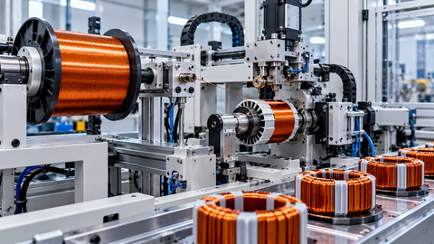
Automated Coil Winding Systems: CNC Overview and Tooling Tips
Automated coil winding systems use computer numerical control (CNC), motion-control equipment, and specialized tooling to wind conductive wire into precise coils for motors, transformers, inductors, sensors, and other electrical components.
They coordinate spindle rotation, wire tension, and guide movement to produce repeatable winding patterns while controlling wire placement and coil geometry.
Modern CNC coil winding machines range from compact equipment for precision inductors to automated production systems for motor stators and transformer windings. Choosing the right machine requires matching the winding method, wire characteristics, tooling design, and control capabilities to the component being manufactured.
Quick Facts About Automated Coil Winding Systems
Feature | Description |
|---|---|
Primary function | Wind conductive wire into controlled coil geometries |
Main control technology | CNC, programmable logic controllers, and motion controllers |
Common conductors | Enamelled copper wire, aluminium wire, and other specified conductors |
Main motion axes | Spindle rotation and wire-guide traverse |
Common winding methods | Linear, flyer, needle, and toroidal winding |
Important tooling | Mandrels, bobbin fixtures, wire guides, nozzles, and tensioners |
Key process variables | Wire tension, winding pitch, spindle speed, and traverse position |
Typical applications | Electric motors, transformers, inductors, relays, and sensors |
Quality considerations | Turn count, wire placement, insulation integrity, and dimensional accuracy |
Automation options | Programmable recipes, automatic wire cutting, part handling, and inspection |
What Are Automated Coil Winding Systems?
Automated coil winding systems are industrial machines that place conductive wire around a bobbin, core, former, stator, or another specified component. The equipment controls the movement of the workpiece and wire so that each turn follows the required path.
A CNC coil winding machine uses programmed motion commands to coordinate its axes. Depending on the design, it may control spindle rotation, traverse movement, wire delivery, tension, indexing, and other process functions. Sensors and feedback devices help the controller maintain the intended motion and detect certain operating faults.
An automatic coil winding machine can also include feeding mechanisms, wire stripping or termination equipment, automatic cutting, part loading, and inspection. These features vary by application, production volume, and the complexity of the finished winding.
Why CNC Coil Winding Technology Matters
Coil performance depends on more than the number of wire turns. Wire placement, spacing, insulation condition, winding geometry, and conductor tension can influence electrical characteristics, thermal behavior, mechanical stability, and manufacturing consistency.
Manual winding may be appropriate for prototypes, repairs, or specialized low-volume work. Automated coil winding equipment becomes particularly useful when a manufacturer needs repeatable winding patterns, controlled turn placement, production traceability, or integration with a larger manufacturing process.
Key reasons manufacturers use CNC winding technology include:
Repeatable turn counts and winding patterns.
Controlled wire placement across multiple layers.
Coordinated spindle and guide movement.
Programmable changeovers between compatible coil designs.
Reduced dependence on continuous manual positioning.
Integration with automated material handling and inspection.
Better process monitoring and fault detection.
Automation does not automatically guarantee a defect-free coil. The result still depends on machine setup, tooling accuracy, conductor quality, insulation handling, and the suitability of the programmed winding recipe.
Understanding CNC Coil Winding: A Simple Explanation
Imagine winding enamelled copper wire around a bobbin. One axis rotates the bobbin, while another moves the wire guide sideways. If the guide advances at the correct rate relative to spindle rotation, the wire forms an orderly layer rather than accumulating in one location.
The CNC controller coordinates these movements according to a programmed pattern. Additional controls maintain wire tension, manage acceleration and deceleration, and coordinate the start and end of the winding operation.
The required movement changes with the coil design. A simple cylindrical coil may need coordinated rotation and linear traverse, whereas a stator winding or toroidal coil may require specialized access, indexing, or wire-feeding mechanisms.
How Automated Coil Winding Systems Work
Step 1: Define the Winding Program
The operator or engineer specifies the coil geometry, turn count, winding direction, traverse limits, layer arrangement, and relevant process settings. The exact parameters depend on the component drawing, conductor specification, and machine capabilities.
For repeat production, the validated recipe can be stored and recalled for compatible jobs. Recipe control helps reduce setup variation, but the program must be verified whenever the component, wire, or tooling changes.
Step 2: Load and Secure the Workpiece
The bobbin, core, former, or stator is positioned in a fixture or spindle assembly. The fixture must locate the component accurately and hold it securely throughout rotation and acceleration.
Poor clamping or incorrect alignment can cause vibration, dimensional variation, wire displacement, or damage to the workpiece.
Step 3: Feed the Wire Through the Guidance System
The conductor travels from its supply package through a tensioning arrangement and wire guides before reaching the winding point. Guide tubes, ceramic eyelets, rollers, and specialized nozzles help direct the wire along the intended path.
The wire path must avoid sharp edges, unnecessary friction, and contact with components that could damage its insulation.
Step 4: Coordinate Rotation and Traverse
The spindle rotates the component or winding mechanism while the traverse axis positions the wire. CNC motion control synchronizes these movements to establish the winding pitch and layer arrangement.
For constant-pitch winding, the relationship between rotation and traverse can remain consistent. More complex patterns require changing the relationship according to spindle position, layer, or coil geometry.
Step 5: Maintain Wire Tension
A tension-control system regulates the pulling force applied to the wire. Depending on the machine, it may use a mechanical brake, controlled drive, dancer mechanism, tension sensor, or a combination of these devices.
Consistent tension helps prevent loose turns and excessive wire stress. The appropriate setting depends on conductor diameter, insulation, material properties, winding speed, and the component design.
Step 6: Complete the Winding and Terminations
At the programmed endpoint, the machine stops or decelerates according to its control sequence. Depending on the application, the wire may then be cut, secured, stripped, or connected to terminals.
Some machines perform these operations automatically; others require a separate station or operator intervention.
Step 7: Inspect and Verify the Finished Coil
Inspection may include turn-count verification, visual checks, dimensional measurements, resistance testing, inductance measurement, or insulation testing as appropriate to the component.
The inspection plan should reflect the electrical design and applicable product requirements rather than relying only on the machine's programmed cycle completion.
CNC Coil Winding Workflow Table
Stage | Machine Function | Quality Objective |
|---|---|---|
Program setup | Load winding parameters | Correct winding geometry |
Workpiece loading | Locate and secure the component | Stable positioning |
Wire preparation | Guide conductor through the feed path | Avoid insulation damage |
Winding | Coordinate rotation and traverse | Accurate turn placement |
Tension regulation | Control wire pulling force | Consistent winding tightness |
Layer transition | Change traverse or winding pattern | Controlled layer arrangement |
Completion | Stop, cut, secure, or terminate wire | Correct winding endpoint |
Inspection | Verify electrical and physical properties | Conformance to specifications |
CNC Coil Winding Machine Architecture and Main Components
CNC or Motion Controller
The controller interprets the winding program and coordinates the machine's motion axes. It manages spindle positioning, traverse movement, programmed acceleration, winding direction, and sequence timing. Depending on the system, a separate PLC may manage auxiliary equipment, safety interlocks, sensors, and automatic handling.
Servo Motors and Drives
Servo motors provide controlled motion to the spindle, traverse, indexing mechanism, or other axes. Their drives use feedback to regulate movement and respond to the programmed commands. Motor sizing and motion profiles must account for the inertia of the workpiece, tooling, and moving assemblies.
Spindle and Workholding Fixture
The spindle rotates the bobbin, former, or component when the selected winding method uses a rotating workpiece. A collet, chuck, mandrel, or custom fixture holds the part in position.
The spindle assembly must maintain suitable alignment and repeatability without deforming the component or obstructing wire placement.
Traverse and Wire-Guide Assembly
The traverse mechanism moves the wire guide along the required path. Linear guides, ball screws, belts, or other motion arrangements may be used, depending on the machine design.
Backlash, friction, vibration, and alignment errors can affect wire placement, especially when the winding requires narrow spacing or frequent direction changes.
Wire Tensioner and Payoff System
The payoff system supplies wire from a spool or package, while the tensioner regulates the force applied during winding. Depending on the machine, tension may be managed mechanically or through an actively controlled mechanism with feedback.
The wire path should maintain stable tension without excessive bending, abrasion, or sudden force changes.
Wire Guides, Nozzles, and Feed Tubes
These components direct the conductor toward the winding location. Their shape, clearance, surface finish, and alignment influence how smoothly the wire travels and whether it contacts the workpiece or surrounding tooling.
Sensors and Safety Equipment
Sensors may detect spindle position, traverse limits, wire breakage, component presence, and other machine conditions. Guards, interlocks, emergency stops, and other protective devices address hazards associated with rotating equipment, moving axes, and electrical systems.
Main Components of Automated Coil Winding Systems
Component | Primary Function | Important Consideration |
|---|---|---|
CNC or motion controller | Coordinates winding movements | Motion synchronization |
PLC and HMI | Manages sequences and operator interaction | Clear controls and diagnostics |
Servo motors and drives | Control axis movement | Torque, inertia, and response |
Spindle assembly | Rotates the workpiece or winding mechanism | Alignment and workholding |
Traverse assembly | Positions the wire guide | Repeatable linear movement |
Payoff system | Supplies conductor | Stable and unobstructed feed |
Wire tensioner | Regulates wire tension | Conductor and insulation limits |
Guide tube or nozzle | Directs wire placement | Clearance and surface finish |
Mandrel or fixture | Supports the coil or component | Geometry and dimensional stability |
Sensors and interlocks | Detect conditions and protect operation | Reliable fault detection |
Types of Automated Coil Winding Machines
Linear Coil Winding Machines
Linear winding machines generally rotate the coil body while feeding wire through a guide that moves along a linear path. This method is suitable for many bobbin-wound coils, cylindrical components, and other geometries accessible to the guide.
Advantages:
Direct control of wire placement along the winding axis.
Suitable for many layered coil designs.
Adaptable to programmable turn patterns.
Tooling considerations include bobbin alignment, traverse travel, guide clearance, and the relationship between spindle rotation and linear movement.
Flyer Coil Winding Machines
Flyer winding machines use a rotating flyer to carry and deliver the wire around a stationary or appropriately supported component. The flyer geometry and wire path determine how the conductor enters the winding area.
Advantages:
Suitable for selected motor and stator winding applications.
Can support automated, repetitive winding cycles.
Allows winding around components that benefit from a rotating wire-delivery mechanism.
Tooling must provide sufficient clearance around the component and manage wire tension, bending, and contact with the flyer or guide surfaces.
Needle Winding Machines
Needle winding machines feed wire through a narrow needle or nozzle that moves into slots or other confined spaces. The method is useful for certain stator designs where conventional flyer access is limited.
Advantages:
Provides access to restricted winding spaces.
Supports automated winding of selected slotted components.
Allows controlled wire placement around stator teeth and poles.
Needle dimensions, approach paths, slot clearance, and wire bend limits must be checked carefully to avoid collisions and insulation damage.
Toroidal Coil Winding Machines
Toroidal winding machines pass wire through or around a ring-shaped magnetic core. Some designs use a rotating shuttle or magazine to carry a loop of wire through the center of the core before distributing it around the circumference.
Advantages:
Designed for ring-shaped cores.
Supports repeatable winding distribution.
Suitable for many toroidal transformers, inductors, and chokes.
The tooling must accommodate the core dimensions, available center opening, wire package, and required winding distribution. Tight core openings can restrict the size of the shuttle and the amount of wire carried per cycle.
Transformer Coil Winding Machines
Transformer coil winding machines are configured for primary and secondary windings on bobbins or other transformer formers. Depending on the transformer design, the machine may support layered winding, sectioned winding, multiple conductors, or specialized insulation placement.
Advantages:
Programmable control of turns and layer transitions.
Support for repeatable winding geometry.
Potential integration with insulation handling and termination processes.
Tooling selection must account for bobbin dimensions, conductor insulation, winding width, layer separation, and the electrical design of the transformer.
Stator Coil Winding Machines
Stator winding equipment is designed for the geometry and slot arrangement of electric motor stators. Depending on the stator, machines may use flyer winding, needle winding, or other specialized winding methods.
Advantages:
Adapted to specific stator and slot geometries.
Supports repeatable winding sequences.
Can integrate with stator handling and downstream assembly.
Tooling must be designed around slot openings, tooth geometry, insulation systems, wire diameter, and the required coil arrangement.
Coil Winding Machine Type Comparison
Machine Type | Winding Method | Common Applications | Main Tooling Priority |
|---|---|---|---|
Linear winding | Rotating workpiece with traversing wire guide | Bobbins, cylindrical coils, inductors | Traverse accuracy |
Flyer winding | Rotating wire-delivery mechanism | Selected motor and stator windings | Flyer clearance and wire path |
Needle winding | Wire delivered through a moving needle | Slotted stators and confined geometries | Needle access and slot clearance |
Toroidal winding | Wire passed through a ring-shaped core | Toroidal transformers and chokes | Core opening and shuttle geometry |
Transformer winding | Layered or sectioned winding on a former | Power and electronic transformers | Layer control and insulation placement |
Stator winding | Specialized winding around stator teeth or slots | Electric motors and generators | Slot geometry and winding access |
These categories can overlap. A transformer winding machine may use linear winding, for example, while a stator winding system may use either flyer or needle technology. Selection should be based on the required winding motion and component geometry, not the machine label alone.
Materials and Tooling Requirements for CNC Coil Winding
Conductive Wire
Enamelled copper wire is widely used for electrical windings, while aluminium conductors and other specified wire types are used in selected applications. Conductor diameter, insulation system, mechanical properties, and allowable bending conditions affect the winding process.
Wire specifications should be matched to the electrical design and the applicable winding-wire requirements. The machine's guides, tensioner, and feed path must be compatible with the chosen conductor.
Bobbins, Cores, and Formers
The component being wound establishes the geometry that the tooling must support. Bobbins and formers require suitable dimensional tolerances, while magnetic cores may need careful handling to avoid chipping or damage.
Fixtures should locate components consistently and provide enough clearance for the wire guide to reach the winding area without interference.
Mandrels and Custom Fixtures
Mandrels support coil shapes that are wound directly on a former or tooling surface. Custom fixtures position irregular parts, hold stators, or provide a repeatable reference for automated loading.
A suitable fixture should be rigid enough to resist movement while avoiding excessive clamping force that could deform the workpiece.
Wire Guides and Ceramic Eyelets
Wire guides control the direction of conductor travel. Ceramic eyelets or other wear-resistant guide materials may be suitable where friction and abrasion need to be controlled.
Guide bores, radii, edges, and alignment should be compatible with the conductor. Damaged or contaminated guides can scratch insulation or produce inconsistent wire feeding.
Insulation and Layer Separation Materials
Certain coil designs require insulating tapes, films, barriers, slot liners, or interlayer materials. These materials must be compatible with the electrical and thermal requirements of the finished component.
Where insulation is applied automatically, its feed path, positioning, and tension need to be coordinated with the winding sequence.
Tooling Compatibility Checklist
Before approving a tooling setup, confirm that:
The fixture matches the component geometry.
The wire guide reaches all required winding positions.
The spindle and traverse have sufficient travel.
The conductor can pass through the tooling without scraping.
The tensioner can operate within the conductor's permitted limits.
Layer transitions and termination points are accessible.
Sensors and guards remain effective throughout the motion cycle.
CNC Coil Winding Tooling Tips for Better Accuracy
Tooling has a direct effect on winding consistency, wire handling, and changeover time. Even a capable CNC controller cannot compensate for a misaligned mandrel, an unsuitable wire guide, or a fixture that allows the component to move.
Match the Mandrel to the Finished Coil Geometry
The mandrel or former should support the intended internal dimensions and provide a stable winding surface. Consider material rigidity, surface finish, dimensional tolerance, and the method used to remove the completed coil.
For removable coils, release features or a suitable split-former design may be necessary. The tooling must also account for insulation thickness and any dimensional change that occurs when the coil is removed or formed.
Minimize Wire-Guide Friction
The wire should travel smoothly through the guide system. Sharp edges, damaged eyelets, contamination, and excessive bends can damage enamel insulation or create inconsistent tension.
Use guides with suitable bore dimensions and smooth contact surfaces. Inspect wear points during setup and maintenance, especially when working with fine wire or delicate insulation systems.
Set Wire Tension for the Actual Conductor
Excessive tension can stretch a conductor, damage insulation, deform a bobbin, or create unwanted stress in the finished winding. Insufficient tension can lead to loose turns, poor layer formation, and unstable wire placement.
Establish tension using the conductor specification and validated process settings. Where practical, check tension at the operating speed because friction and acceleration can cause it to differ from a stationary measurement.
Synchronize Spindle Rotation and Traverse
For a regular helical winding, traverse movement must maintain the intended relationship to spindle rotation. If the traverse moves too far during each revolution, the turns may leave gaps; if it moves too little, adjacent turns may overlap or accumulate unevenly.
More complex windings may require programmed changes in pitch or coordinated movement at particular spindle angles. Verify the resulting pattern over the entire coil, including layer transitions and reversal points.
Control Acceleration and Deceleration
Abrupt changes in speed can create tension fluctuations, wire displacement, and mechanical vibration. Motion profiles should allow the spindle and traverse to accelerate and decelerate in a coordinated manner.
The correct profile depends on machine inertia, tooling mass, wire properties, and the required production rate. Increasing speed without validating these factors may reduce quality rather than improve throughput.
Validate Tooling Changes Before Production
A change in wire diameter, bobbin size, coil width, or winding pattern may require a different guide, fixture, tension setting, or program. After a changeover, verify the first winding for turn placement, layer structure, wire damage, and the relevant electrical characteristics.
A controlled first-piece approval process helps prevent setup errors from affecting an entire production batch.
CNC Coil Winding Tooling Comparison Table
Tooling Element | Main Purpose | Common Setup Problem | Recommended Check |
|---|---|---|---|
Mandrel or former | Establishes coil geometry | Incorrect dimensions or difficult removal | Verify dimensions and release method |
Workholding fixture | Locates the component | Misalignment or movement | Check concentricity and clamping |
Wire guide | Directs conductor travel | Scraping or inconsistent feed | Inspect bore and surface condition |
Tensioner | Controls wire pulling force | Excessive or unstable tension | Verify tension under operating conditions |
Traverse mechanism | Positions wire across the coil | Uneven pitch or backlash | Check motion synchronization |
Flyer or needle | Delivers wire to the winding area | Collision or restricted access | Verify clearance throughout the cycle |
Insulation applicator | Positions insulating material | Wrinkles or incorrect placement | Check feed alignment and sequence |
CNC Coil Winding vs. Manual Coil Winding
Manual winding and CNC winding are different production approaches rather than universally competing technologies. Manual methods can be practical for prototypes, repair work, and specialized low-volume components. CNC equipment is generally more appropriate when a process benefits from programmed motion, repeatable geometry, and controlled production sequences.
Comparison Factor | CNC Coil Winding | Manual Coil Winding |
|---|---|---|
Motion control | Programmed and coordinated axes | Operator-controlled movement |
Repeatability | Supports consistent programmed patterns | Depends heavily on operator technique |
Changeover | Requires suitable tooling and recipe adjustment | May be straightforward for simple designs |
Production monitoring | Can integrate sensors and process records | Often requires separate recording and inspection |
Complex patterns | Can automate coordinated movement | May require specialized manual techniques |
Initial setup | Requires machine configuration and program validation | May need simpler equipment and fixtures |
Operator role | Setup, supervision, quality checks, and maintenance | Direct winding and frequent manual handling |
Typical suitability | Repeat production and complex motion requirements | Prototypes, repairs, and selected low-volume tasks |
The decision should consider total process requirements, not only cycle speed. Tooling preparation, programming, inspection, material handling, and changeover time can all influence overall productivity.
Benefits and Advantages of Automated Coil Winding Systems
Improved Winding Repeatability
Programmable spindle and traverse movements help reproduce the intended winding pattern. Consistency still depends on accurate tooling, stable tension, correct wire specifications, and appropriate process validation.
Better Control of Coil Geometry
CNC movement can regulate traverse pitch, winding width, and layer transitions. This is useful when coil dimensions and conductor placement affect electrical performance or fit within an assembly.
Reduced Manual Positioning
Automated movement reduces the need for an operator to guide every turn manually. This can make repetitive production more consistent and allow operators to focus on setup, inspection, and process supervision.
Flexible Production Recipes
Compatible machine configurations can store multiple winding programs for different components. Recipe-based changeovers can reduce repeated manual adjustments, although new tooling or process validation may still be necessary.
Integration with Quality Control
Sensors, counters, electrical testers, and inspection systems can be integrated into the production process. Depending on the equipment, these systems can identify certain faults, record process information, or prevent a component from advancing when a required check fails.
Potential for Higher Throughput
Automation can reduce manual handling and support coordinated motion at production speeds suited to the component. Actual throughput depends on winding complexity, loading and unloading, termination steps, inspection, and downtime.
Industry Applications of Automated Coil Winding Systems
Electric Motor Manufacturing
Motor production uses winding equipment to place conductors in stator slots or around other specified components. Flyer and needle winding are common approaches for particular stator geometries, while other motor coils may use linear or specialized winding methods.
Tooling must account for slot openings, insulation systems, tooth geometry, and the required conductor arrangement.
Transformer Manufacturing
Transformer coils require controlled turn counts and winding arrangements. Depending on the design, the process may involve multiple winding sections, insulation layers, different conductor dimensions, or specialized conductor configurations.
A transformer coil winding machine must support the component's electrical design, insulation requirements, and mechanical geometry.
Inductors and Chokes
Inductors and chokes use coils to establish magnetic characteristics required by an electrical circuit. Winding geometry, turn count, spacing, and core arrangement influence the resulting electrical behavior.
CNC winding equipment can support repeatable production of bobbin-mounted and toroidal components.
Automotive Electrical Components
Automotive applications include selected motors, actuators, ignition components, relays, sensors, and electromagnetic assemblies. Production requirements vary by component, with emphasis on repeatability, process control, and the relevant qualification and testing procedures.
Electronics and Sensor Manufacturing
Small coils used in sensors, relays, communication devices, and electronic assemblies may require fine wire and carefully controlled placement. Appropriate guide geometry and tension control are particularly important when the conductor is delicate or the available winding space is limited.
Generator and Industrial Electromagnetic Equipment
Generators and other industrial electromagnetic equipment use windings designed for their electrical and mechanical operating requirements. The winding method depends on conductor dimensions, component geometry, insulation, and manufacturing sequence.
Industry Applications Table for CNC Coil Winding Machines
Industry | Example Components | Key Winding Requirement |
|---|---|---|
Electric motors | Stators and motor coils | Slot access and conductor placement |
Transformers | Primary and secondary coils | Layer arrangement and insulation |
Power electronics | Inductors and chokes | Controlled turns and coil geometry |
Automotive | Relays, actuators, and selected motor components | Repeatability and process verification |
Sensors and electronics | Sensor coils and small inductors | Fine-wire handling and accurate placement |
Generators | Electromagnetic windings | Conductor arrangement and insulation integrity |
Industrial controls | Solenoids and electromagnetic assemblies | Consistent geometry and electrical characteristics |
Industry Standards and Safety for Coil Winding Equipment
Applicable standards depend on the machine design, the finished electrical component, the installation environment, and the market where the equipment operates. Standards should be selected and assessed by qualified engineering and compliance personnel.
IEC 60204-1: Safety of Machinery — Electrical Equipment of Machines
IEC 60204-1 addresses electrical equipment requirements for machinery, including relevant aspects of electrical protection, control circuits, operator interfaces, wiring, and documentation. Its application must be considered alongside other requirements relevant to the machine's hazards.
ISO 12100: Safety of Machinery — Risk Assessment and Risk Reduction
ISO 12100 provides a framework for identifying machinery hazards, assessing risks, and determining appropriate risk-reduction measures. It is relevant to the design and evaluation of automated winding equipment with rotating parts, moving axes, and operator access points.
IEC 60317: Specifications for Particular Types of Winding Wires
The IEC 60317 series specifies requirements for particular types of winding wire. The applicable part depends on the conductor and insulation construction, so manufacturers should confirm the specification that matches the selected wire.
IEC 61858: Electrical Insulation Systems — Thermal Evaluation of Modifications to an Established Electrical Insulation System
The IEC 61858 series addresses thermal evaluation of modifications to established electrical insulation systems. Its relevance depends on the design and qualification requirements of the finished electrical component.
Machine Safety Practices
Automated coil winding equipment should have appropriate guarding, emergency-stop functions, interlocks, electrical protection, and safe procedures for setup and maintenance. Risk assessments should consider entanglement, pinch points, rotating tooling, wire breakage, stored energy, and unexpected machine movement.
Operators should not reach into moving machinery or bypass protective devices to correct wire-feed problems. Setup, adjustment, and maintenance must follow the machine's documented safety procedures.
Common CNC Coil Winding Problems and Solutions
Winding defects can originate from the machine, tooling, wire supply, program, or component itself. Troubleshooting should begin by identifying the defect pattern and checking the relevant process variables rather than making several adjustments at once.
Problem | Possible Cause | Recommended Corrective Action |
|---|---|---|
Uneven winding layers | Incorrect traverse pitch or alignment | Verify axis synchronization and guide position |
Loose turns | Insufficient or unstable wire tension | Check tension control and wire-feed resistance |
Broken wire | Excessive tension, sharp contact points, or unsuitable bending | Inspect the wire path and verify conductor limits |
Damaged enamel insulation | Abrasive guides, sharp edges, or excessive force | Inspect guide surfaces and handling conditions |
Wire bunching | Incorrect traverse limits or reversal settings | Verify the winding program and traverse travel |
Inconsistent turn count | Incorrect program settings or counting faults | Check the recipe and counting method |
Poor layer transitions | Incorrect traverse reversal or transition sequence | Validate the programmed motion profile |
Coil dimensional variation | Fixture movement or incorrect tooling dimensions | Check workholding, alignment, and tooling |
Excessive vibration | Imbalance, loose fixtures, or unsuitable motion profiles | Inspect the mechanical assembly and motion settings |
Repeated wire-feed interruptions | Spool drag, guide obstruction, or tensioner problems | Inspect the payoff path and tension-control system |
Inconsistent electrical results | Winding geometry, conductor, or insulation variation | Review process records and applicable electrical tests |
How to Choose an Automated Coil Winding Machine
Selecting a CNC coil winding machine requires a clear understanding of the component, production requirements, and process limitations. A machine suited to small inductors may not provide the access, tooling capacity, or wire-handling arrangements required for a motor stator or large transformer.
Selection Factor | What to Evaluate | Why It Matters |
|---|---|---|
Component geometry | Bobbin, stator, toroidal core, or custom former | Determines winding method and tooling |
Wire specification | Material, diameter, insulation, and bend limits | Establishes feed and tension requirements |
Winding pattern | Turn count, pitch, layers, and direction | Determines CNC motion requirements |
Number of axes | Spindle, traverse, indexing, and auxiliary movement | Affects pattern flexibility |
Tension control | Mechanical or feedback-based regulation | Influences winding consistency |
Tooling compatibility | Mandrels, guides, nozzles, and fixtures | Determines access and changeover needs |
Production requirements | Output targets, batch sizes, and changeovers | Influences automation level |
Quality verification | Electrical tests and dimensional inspection | Establishes process acceptance criteria |
Automation integration | Loading, cutting, termination, and inspection | Determines the overall production workflow |
Maintenance capability | Spare parts, diagnostics, and technical support | Affects long-term operation |
Safety requirements | Guards, interlocks, risk controls, and applicable standards | Supports safe machine operation |
Match the Winding Method to the Component
Begin by confirming how the wire must reach the winding surface. Linear winding is suitable for many bobbin-based designs, while flyer and needle winding address different motor and stator geometries. Toroidal winding requires tooling capable of passing wire through a ring-shaped core.
Evaluate CNC Programming and Motion Control
Confirm that the controller supports the required winding pattern, axis synchronization, layer transitions, and repeatable positioning. More complex coils may require variable pitch, indexed movement, or coordinated motion beyond a basic rotation-and-traverse arrangement.
Assess Tooling and Changeover Requirements
Determine which mandrels, guides, fixtures, and nozzles are required for each component family. Quick-change tooling may be useful in mixed-product manufacturing, but it must preserve alignment and repeatability after each changeover.
Verify Process Capability Before Production
A machine demonstration or acceptance trial should use representative components and the intended conductor wherever practical. Assess the completed coil for geometry, wire placement, insulation condition, electrical properties, and cycle consistency.
Production approval should be based on the actual component requirements rather than the machine's nominal speed alone.
Maintenance Best Practices for CNC Coil Winding Equipment
Inspect Wire Guides and Tooling
Check guides, nozzles, eyelets, mandrels, and fixtures for wear, contamination, deformation, and sharp edges. Damaged tooling can cause repeated wire defects even when the motion program is correct.
Check Spindle and Traverse Alignment
Inspect workholding, bearings, linear guides, couplings, and relevant mechanical components according to the maintenance schedule. Alignment changes and mechanical play can affect winding pitch, coil dimensions, and repeatability.
Verify Tension-Control Performance
Check the payoff mechanism, tension sensor where fitted, braking arrangement, and wire-feed path. Tension behavior should be assessed under representative operating conditions, including acceleration and deceleration.
Maintain Servo Systems and Motion Components
Review alarms, position errors, abnormal vibration, and signs of excessive friction or mechanical looseness. Maintenance should follow the equipment manufacturer's procedures and account for the motion system's design.
Back Up Programs and Machine Parameters
Maintain controlled backups of validated winding recipes, machine settings, and relevant configuration data. Changes should be documented so that production can be restored consistently and unauthorized modifications can be identified.
Test Safety Devices
Inspect guards, interlocks, emergency stops, and other protective devices according to the machine's safety and maintenance procedures. Any fault in a safety function should be addressed before the equipment returns to normal production.
Review Finished-Coil Quality
Track recurring defects, dimensional variation, electrical test results, and wire-break events. These patterns can help distinguish problems caused by tooling wear, material variation, incorrect programs, or mechanical deterioration.
Limitations of Automated Coil Winding Systems
CNC winding equipment improves motion control, but it introduces its own engineering and operating requirements.
Initial engineering effort: The machine, tooling, and programs must be configured for the component.
Tooling dependence: Specialized winding geometries may require custom fixtures, guides, or wire-delivery mechanisms.
Material sensitivity: Fine wire and delicate insulation can be damaged by unsuitable tension or contact surfaces.
Changeover requirements: Different components may require mechanical adjustments, new tooling, and program validation.
Maintenance needs: Servo systems, tensioners, guides, sensors, and moving assemblies require inspection.
Process constraints: Some geometries may be difficult to wind because of limited access, tight bend radii, or restricted space.
Quality verification: Programmed movement alone does not prove that the finished coil meets electrical or insulation requirements.
Production economics: Automation may be less suitable for very small quantities or frequently changing designs when setup and tooling effort outweigh the production benefits.
A successful implementation balances motion capability, tooling complexity, material handling, inspection requirements, and the actual production mix.
Future Trends in Automated Coil Winding Systems
More Flexible Motion Programming
Modern motion-control capabilities support coordinated axes, programmable winding patterns, and controlled transitions between layers. These capabilities can make it easier to accommodate complex geometries when the machine's mechanical design supports them.
Improved Process Monitoring
Sensors can monitor variables such as tension, spindle position, wire presence, and machine condition. When properly integrated, this information can help identify abnormal conditions and improve process traceability.
Integrated Inspection
Manufacturers can combine winding operations with turn counting, dimensional checks, electrical testing, and automated handling. The extent of integration depends on component requirements and the available production equipment.
More Adaptable Tooling
Modular fixtures, replaceable guides, and configurable workholding can simplify production changes across compatible component families. Tooling still needs to be validated for each relevant wire and coil geometry.
Data-Driven Process Optimization
Production records can help manufacturers identify recurring defects, compare validated recipes, and investigate changes in cycle consistency. Data analysis is most useful when measurements are reliable and linked to specific machine settings and component requirements.
Frequently Asked Questions About Automated Coil Winding Systems
1. What is an automated coil winding system?
An automated coil winding system uses controlled mechanical movement to place conductive wire around a bobbin, core, former, or other component. CNC or motion-control equipment coordinates the winding process to achieve a specified turn count and geometry.
2. What is the difference between a CNC coil winding machine and an automatic coil winding machine?
A CNC coil winding machine emphasizes programmed and coordinated axis movement. An automatic coil winding machine may also include automated feeding, cutting, termination, part handling, and inspection; not every automatic machine uses the same CNC architecture.
3. Which industries use CNC coil winding equipment?
Common applications include electric motor manufacturing, transformer production, power electronics, automotive electrical components, sensors, relays, and industrial electromagnetic equipment. The appropriate machine depends on the component geometry and winding requirements.
4. What does a wire tensioner do in a coil winding machine?
A wire tensioner regulates the pulling force applied to the conductor as it enters the winding area. Proper tension helps maintain orderly turns while reducing the risk of wire breakage, insulation damage, or loose winding layers.
5. What tooling is required for CNC coil winding?
Common tooling includes mandrels, bobbin fixtures, workholding devices, wire guides, ceramic eyelets, nozzles, and tension-control components. Specialized machines may also require flyers, needles, toroidal shuttles, or indexing fixtures.
6. How does CNC control improve winding accuracy?
CNC control coordinates spindle rotation and wire-guide movement according to a programmed pattern. This helps maintain turn placement, traverse pitch, and layer transitions, provided that the machine, tooling, and wire-feed system are correctly configured.
7. What causes uneven winding layers?
Uneven layers can result from incorrect traverse synchronization, misaligned tooling, unstable tension, mechanical play, or an unsuitable winding program. Inspecting the wire path and motion settings helps identify the underlying cause.
8. Can one coil winding machine manufacture different coil designs?
Some machines can produce multiple designs by changing programs and compatible tooling. The available range depends on spindle capacity, axis travel, wire-handling capability, winding method, and the geometry of each component.
9. How is the quality of a finished coil checked?
Inspection may include turn-count verification, visual examination, dimensional measurement, resistance testing, inductance measurement, and insulation testing. The required checks depend on the electrical design and the applicable product specifications.
10. Which standards are relevant to coil winding machines?
IEC 60204-1 addresses electrical equipment of machinery, ISO 12100 provides a machinery risk-assessment framework, and the relevant IEC 60317 specification may apply to the winding wire. The correct standards and compliance requirements depend on the equipment, conductor, finished component, and installation market.
Conclusion
Automated coil winding systems combine CNC motion control, wire-tension regulation, and application-specific tooling to produce repeatable electrical windings. Choosing the correct winding method, guide geometry, fixture, and motion program is essential for achieving the intended coil dimensions and electrical properties. With validated recipes, appropriate maintenance, and suitable quality checks, manufacturers can integrate coil winding equipment into reliable and repeatable production processes.

Related Post...
Industrial 3D Printing Materials: Selection Guide and Properties
Updated: October 24, 2026
Read More