Vacuum Brazing Furnaces Guide: Process, Types and Applications
A vacuum brazing furnace is an industrial heating system that joins two or more metal components using a filler metal inside a controlled low-pressure environment. The process uses heat and vacuum conditions to promote clean, strong joints while limiting oxidation and contamination.
It is widely used in aerospace, automotive, electronics, heat exchangers, and precision manufacturing.
Vacuum brazing is particularly useful for complex assemblies containing multiple joints that require consistent heating, controlled filler-metal flow, and minimal surface contamination. Understanding furnace designs, processing stages, material compatibility, and operating requirements helps determine where this technology is appropriate.
Quick Facts About Vacuum Brazing Furnaces
The following table summarizes the essential characteristics of vacuum brazing furnace technology.
Feature | Details |
|---|---|
Equipment Name | Vacuum Brazing Furnace |
Industrial Process | Vacuum Furnace Brazing |
Primary Function | Joining metal components using filler metal |
Heating Method | Electrical resistance heating |
Processing Environment | Controlled low-pressure atmosphere |
Typical Temperature Range | Approximately 600°C–1,200°C, depending on materials and filler metals |
Common Base Materials | Stainless steel, nickel alloys, copper, and titanium |
Common Filler Metals | Silver, copper, nickel, and gold-based alloys |
Furnace Configurations | Horizontal, vertical, batch, and specialized continuous systems |
Hot Zone Materials | Graphite and molybdenum |
Main Applications | Aerospace, automotive, electronics, and industrial heat exchangers |
Key Advantages | Clean joints, controlled heating, and reduced oxidation |
Important Parameters | Temperature, vacuum level, heating rate, and holding time |
What Is a Vacuum Brazing Furnace?
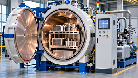
A vacuum brazing furnace is specialized industrial equipment designed to join metal components under controlled vacuum conditions. It heats an assembled workpiece until a compatible filler metal melts and flows into the joint clearance through capillary action.
Unlike welding, brazing does not require the base materials to melt. The filler metal has a lower melting temperature than the components being joined, allowing the assembly to maintain its overall shape while forming a metallurgical connection.
The vacuum environment reduces the presence of oxygen and other reactive gases that can interfere with filler-metal wetting and joint formation. It can also reduce the need for conventional brazing fluxes in compatible material systems.
A typical vacuum brazing furnace includes an insulated heating chamber, electrical heating elements, vacuum pumps, temperature controls, cooling arrangements, and monitoring instruments.
The equipment is used when manufacturers need repeatable thermal processing, clean surfaces, and reliable joints across complex metal assemblies.
Why Vacuum Brazing Technology Matters in Industrial Manufacturing
Industrial assemblies often contain multiple metal components with different shapes, thicknesses, and connection requirements. Joining these components without introducing excessive distortion or contamination can be challenging.
Vacuum brazing provides a controlled thermal environment in which several joints can be formed during one furnace cycle. This makes it particularly useful for assemblies containing narrow passages, intricate geometries, and multiple connection points.
Its main industrial advantages include:
Reduced oxidation: Vacuum conditions limit exposure to atmospheric oxygen during heating.
Flux-free processing: Compatible material combinations can be brazed without conventional flux.
Complex joint formation: Capillary action allows filler metal to enter appropriately designed narrow joint clearances.
Uniform heating: The furnace heats the assembly according to a controlled thermal cycle.
Repeatable processing: Programmable temperature and vacuum controls support consistent production conditions.
Clean finished components: The absence of conventional flux residues reduces certain post-brazing cleaning requirements.
However, vacuum conditions alone do not guarantee a successful joint. Surface preparation, filler-metal selection, joint geometry, and process control remain essential.
How Does a Vacuum Brazing Furnace Work?
Vacuum brazing combines controlled heating, reduced atmospheric pressure, and the melting behavior of a compatible filler metal.
The process is generally performed through several stages.
1. Component Preparation and Cleaning
Before brazing, metal components must be cleaned to remove grease, oils, machining residues, surface oxides, and other contaminants.
The surfaces must be suitable for filler-metal wetting. Contamination can prevent the filler metal from spreading properly and entering the joint clearance.
Cleaning methods depend on the base material and production requirements.
2. Component Assembly and Filler-Metal Placement
The prepared components are positioned according to the required joint design.
The brazing filler metal is placed at or near the intended joint. It may be supplied as a preform, wire, foil, ring, or paste, depending on the material and application.
Fixtures can be used to maintain alignment and prevent movement during heating.
3. Vacuum Chamber Evacuation
The assembled workpieces are loaded into the furnace chamber, which is then sealed.
Vacuum pumps remove air and other gases from the chamber. This reduces the amount of oxygen and moisture available to react with heated metal surfaces.
The required vacuum level depends on the base materials, filler metal, temperature, and process specifications.
4. Controlled Heating
Electrical heating elements raise the temperature according to a programmed heating cycle.
The heating rate must account for component dimensions, thermal mass, material properties, and assembly geometry.
Some processes include intermediate temperature holds to allow the workpiece to reach a suitable thermal condition before brazing begins.
5. Filler-Metal Melting and Flow
When the assembly reaches the brazing temperature, the filler metal melts while the base materials remain solid.
The liquid filler metal wets compatible surfaces and flows into the joint clearance through capillary action.
Proper joint clearance and surface cleanliness are essential for effective filler distribution.
6. Cooling and Solidification
After the required brazing period, the assembly is cooled under controlled conditions.
Some vacuum furnaces use inert-gas backfilling to accelerate cooling. The cooling rate must be suitable for the materials and any required metallurgical properties.
7. Inspection and Quality Verification
After cooling, the brazed assembly is removed and inspected.
Inspection methods may include visual examination, dimensional checks, leak testing, radiographic examination, and other techniques appropriate to the joint design.
The following table summarizes the complete processing sequence.
Process Stage | Main Activity | Primary Objective |
|---|---|---|
Preparation | Cleaning metal components | Remove contaminants |
Assembly | Position components and filler metal | Establish correct joint geometry |
Evacuation | Remove chamber gases | Reduce oxidation and contamination |
Heating | Raise temperature gradually | Reach the required brazing condition |
Brazing | Melt and distribute filler metal | Form the joint |
Cooling | Controlled temperature reduction | Solidify the filler metal |
Inspection | Examine completed assembly | Verify joint quality |
Main Types of Vacuum Brazing Furnaces
Vacuum brazing furnaces are classified according to their chamber construction, loading orientation, heating-zone materials, and production arrangement. These classifications describe different design characteristics rather than entirely separate brazing processes.
1. Cold-Wall Vacuum Brazing Furnace
A cold-wall furnace uses a water-cooled outer chamber surrounding an insulated internal hot zone.
The heating elements and insulation are located inside the chamber, while the external vessel remains comparatively cool because of its cooling system.
This arrangement is widely used in industrial vacuum heat treatment and brazing applications.
Main characteristics:
Water-cooled external chamber.
Insulated internal heating zone.
Controlled heating and cooling arrangements.
Suitable for a range of industrial processing temperatures.
Typical applications: Aerospace components, stainless steel assemblies, industrial heat exchangers, and precision metal joining.
2. Hot-Wall Vacuum Brazing Furnace
A hot-wall configuration uses a different chamber-heating arrangement in which the furnace walls are heated as part of the thermal system.
Its suitability depends on the required temperature uniformity, chamber construction, vacuum conditions, and material compatibility.
Hot-wall designs are less commonly encountered in general industrial vacuum brazing than cold-wall configurations.
Main characteristics:
Heated chamber-wall arrangement.
Different thermal behavior from cold-wall systems.
Requires careful evaluation of chamber materials and operating conditions.
Application-specific construction.
Typical applications: Specialized thermal processing and selected industrial heating environments.
3. Graphite Hot-Zone Furnace
Graphite hot-zone furnaces use graphite heating elements and insulation within the vacuum chamber.
Graphite systems can support high-temperature processing and are used for applications where their thermal characteristics and material compatibility are appropriate.
However, graphite can introduce contamination concerns for certain reactive metals and applications.
Main characteristics:
Graphite heating elements and insulation.
Suitable for many high-temperature applications.
Thermal properties appropriate for industrial batch processing.
Requires consideration of carbon contamination and material compatibility.
Typical applications: Industrial metal brazing, selected heat-resistant alloy assemblies, and compatible high-temperature processes.
4. All-Metal Hot-Zone Furnace
All-metal hot-zone furnaces generally use refractory metal heating elements and internal shields, commonly based on molybdenum.
They are selected when graphite contamination must be avoided or when the material system requires a compatible metallic heating environment.
Main characteristics:
Metallic heating elements and thermal shields.
Suitable for applications requiring controlled contamination conditions.
Compatible with selected reactive-metal processing requirements.
Requires appropriate vacuum conditions and thermal management.
Typical applications: Aerospace components, titanium assemblies, precision metal parts, and selected high-purity applications.
5. Horizontal Vacuum Brazing Furnace
Horizontal furnaces use a chamber and loading arrangement in which components enter horizontally.
They are suitable for many industrial assemblies, particularly those with large footprints or long geometries.
Main characteristics:
Horizontal loading orientation.
Suitable for flat, elongated, and large assemblies.
Flexible fixture arrangements.
Common in industrial batch production.
Typical applications: Heat exchangers, aerospace assemblies, automotive components, and industrial tooling.
6. Vertical Vacuum Brazing Furnace
Vertical furnaces use an upright chamber configuration, with loading typically arranged through the top or bottom.
This arrangement can be useful for components that require vertical positioning or where the available manufacturing space favors an upright chamber.
Main characteristics:
Vertical loading orientation.
Suitable for certain tall or cylindrical components.
Different fixture and handling requirements from horizontal designs.
Can accommodate specialized component geometries.
Typical applications: Cylindrical assemblies, specialized industrial components, and selected aerospace structures.
Vacuum Brazing Furnace Type Comparison
The following table compares the major furnace design configurations and their typical characteristics.
Furnace Configuration | Main Design Feature | Primary Consideration | Typical Application |
|---|---|---|---|
Cold-Wall | Water-cooled outer chamber | Flexible industrial processing | Aerospace and manufacturing |
Hot-Wall | Heated chamber-wall arrangement | Specialized thermal requirements | Selected industrial processes |
Graphite Hot Zone | Graphite heating elements | Carbon compatibility | High-temperature brazing |
All-Metal Hot Zone | Refractory metal heating elements | Low-contamination processing | Titanium and precision assemblies |
Horizontal | Horizontal loading | Large or elongated components | Heat exchangers |
Vertical | Upright loading | Component geometry and handling | Cylindrical assemblies |
A furnace can combine several of these characteristics. For example, a horizontal cold-wall furnace may use either a graphite or all-metal hot zone.
Main Components of a Vacuum Brazing Furnace
A vacuum brazing furnace contains several integrated components that work together to maintain the required atmosphere, temperature, and processing conditions.
Component | Main Function | Technical Importance |
|---|---|---|
Vacuum Chamber | Encloses the workpiece | Maintains a controlled processing environment |
Heating Elements | Generate thermal energy | Raise the assembly to brazing temperature |
Hot Zone | Contains heating elements and insulation | Supports controlled heat distribution |
Vacuum Pumps | Remove gases from the chamber | Establish the required pressure |
Vacuum Valves | Control gas flow and pumping connections | Manage evacuation and isolation |
Temperature Sensors | Measure furnace temperature | Support thermal monitoring |
Control System | Manages the programmed cycle | Coordinates processing parameters |
Cooling System | Removes heat | Controls cooling conditions |
Gas Backfill System | Introduces selected gases | Supports controlled cooling |
Loading Fixtures | Hold components in position | Maintain assembly alignment |
The performance of the complete system depends on the correct integration of these components. A suitable vacuum pump alone cannot compensate for poor chamber sealing, incorrect temperature measurement, or unsuitable furnace loading.
Materials and Filler Metals Used in Vacuum Brazing
Material compatibility is one of the most important considerations in vacuum brazing. The base metals, filler metals, and furnace hot-zone materials must all be suitable for the selected thermal cycle.
Common Base Materials
Stainless steel: Stainless steel is widely used in vacuum brazing for industrial equipment, heat exchangers, and precision assemblies.
Nickel-based alloys: These materials are used in high-temperature and corrosion-resistant components, including selected aerospace and energy applications.
Copper and copper alloys: Their thermal and electrical properties make them suitable for heat exchangers, electrical assemblies, and industrial cooling components.
Titanium: Titanium can be vacuum brazed for specialized applications, but its strong reactivity at elevated temperatures requires carefully controlled processing conditions.
Carbon and alloy steels: Selected grades can be joined using compatible filler metals and appropriate furnace cycles.
Common Brazing Filler Metals
Filler Metal Family | General Characteristics | Typical Applications |
|---|---|---|
Silver-Based | Good wetting and relatively lower brazing temperatures | Copper alloys and selected stainless steel joints |
Copper-Based | Useful thermal and joining characteristics | Stainless steel and compatible alloy assemblies |
Nickel-Based | Suitable for selected high-temperature applications | Heat-resistant alloys and aerospace components |
Gold-Based | Used in specialized precision joining applications | Electronics and selected high-reliability assemblies |
Filler-metal selection must account for melting range, wetting behavior, joint strength, corrosion resistance, service temperature, and interaction with the base materials.
Some elements, including zinc, cadmium, and lead, have relatively high vapor pressures under vacuum brazing conditions. Their presence can create evaporation and contamination problems, so filler-metal composition requires careful evaluation.
Vacuum Brazing vs Other Metal Joining Processes
Vacuum brazing is often compared with welding, conventional furnace brazing, and controlled-atmosphere brazing. Although all these methods can join metal components, their heating environments and joining mechanisms differ.
Process | Joining Mechanism | Processing Environment | Main Characteristic |
|---|---|---|---|
Vacuum Brazing | Liquid filler metal flows through capillary action | Vacuum chamber | Reduced oxidation and flux contamination |
Welding | Base materials are fused | Local or controlled atmosphere | Direct fusion of base materials |
Torch Brazing | Filler metal melts using a torch | Ambient or controlled environment | Localized heating |
Induction Brazing | Filler metal melts through induction heating | Ambient or controlled environment | Localized electromagnetic heating |
Controlled-Atmosphere Brazing | Filler metal melts in a controlled gas atmosphere | Protective gas environment | Atmosphere-controlled joining |
Vacuum brazing is particularly useful when clean assemblies and complex joint arrangements are required. Welding may be more appropriate when a fusion joint is necessary, while torch and induction brazing can be suitable for localized joining operations.
Industrial Applications of Vacuum Brazing Furnaces
Vacuum brazing furnaces support several industries where component reliability, controlled processing, and complex metal assemblies are required.
1. Aerospace Manufacturing
Aerospace manufacturing uses vacuum brazing for selected heat-resistant alloy assemblies, engine components, and precision structures.
The process can join intricate metal geometries while limiting surface oxidation. Applications may include turbine-related components, cooling structures, and specialized engine assemblies.
Material compatibility and joint qualification are especially important because aerospace components may operate under demanding thermal and mechanical conditions.
2. Automotive Manufacturing
Automotive production uses vacuum brazing for components that require multiple joints and controlled thermal processing.
Typical applications include:
Automotive heat exchangers.
Cooling system components.
Turbocharger-related assemblies.
Stainless steel components.
Selected transmission and engine parts.
The process can support consistent joining across assemblies containing numerous closely spaced joints.
3. Heat Exchanger Manufacturing
Heat exchanger manufacturing is one of the important applications of vacuum brazing.
Heat exchangers often contain thin metal plates, channels, and internal passages that must be joined without blocking their flow paths.
Vacuum brazing allows compatible components to be joined simultaneously, producing assemblies used in industrial cooling, refrigeration, energy systems, and thermal management equipment.
4. Electronics and Electrical Manufacturing
Electronics manufacturing uses vacuum brazing for selected metal enclosures, electrical connections, and thermal management assemblies.
The controlled processing environment can be useful where surface cleanliness and precise joint formation are required.
Applications include specialized electronic housings, conductive assemblies, and selected semiconductor-related equipment components.
5. Medical Equipment Manufacturing
Certain medical equipment components require precision metal joining and controlled surface conditions.
Vacuum brazing may be used for compatible stainless steel and other metal assemblies, including selected instrument components and specialized equipment structures.
Material compatibility, cleaning procedures, and validation requirements must be established according to the intended application.
6. Industrial Machinery and Tooling
Industrial machinery manufacturers use vacuum brazing to join selected metal components in specialized equipment and tooling assemblies.
Applications can include:
Precision cutting tools.
Industrial heat treatment fixtures.
Specialized metal structures.
Carbide-to-metal assemblies.
Selected wear-resistant components.
The process can help join materials with different physical properties when an appropriate filler metal and joint design are available.
Common Vacuum Brazing Problems and Their Solutions
Vacuum brazing requires control over multiple interacting variables. A problem in surface preparation, joint geometry, furnace operation, or cooling can affect the final assembly.
The following table outlines common process difficulties.
Common Problem | Possible Cause | Recommended Approach |
|---|---|---|
Incomplete Filler Flow | Poor wetting or incorrect joint clearance | Review surface preparation and joint geometry |
Porosity | Trapped gases or contamination | Improve cleaning and evacuation procedures |
Oxidation | Insufficient vacuum or unsuitable process conditions | Review vacuum performance and atmosphere control |
Excessive Filler Flow | Incorrect filler quantity or joint design | Review filler placement and joint clearance |
Component Distortion | Uneven heating or unsuitable fixturing | Improve fixture design and thermal uniformity |
Joint Cracking | Thermal stress or incompatible materials | Review material selection and cooling cycle |
Filler-Metal Evaporation | Unsuitable filler composition or excessive temperature | Evaluate vapor pressure and brazing parameters |
Uneven Joint Formation | Poor assembly alignment or temperature distribution | Improve loading and fixture arrangements |
Successful troubleshooting requires identifying the underlying cause rather than simply increasing the brazing temperature or vacuum level.
How to Choose a Vacuum Brazing Furnace
Selecting a vacuum brazing furnace requires matching its technical capabilities with the materials, component dimensions, production requirements, and quality expectations of the application.
The following factors provide a practical evaluation framework.
Selection Factor | What to Evaluate | Why It Matters |
|---|---|---|
Operating Temperature | Required brazing temperature | Determines heating system suitability |
Vacuum Performance | Required pressure and pumping capability | Influences atmosphere quality |
Chamber Dimensions | Component size and fixture arrangement | Determines usable processing space |
Hot-Zone Material | Graphite or all-metal construction | Affects material compatibility |
Temperature Uniformity | Distribution throughout the hot zone | Supports consistent joint formation |
Loading Configuration | Horizontal or vertical arrangement | Matches component geometry |
Cooling Capability | Gas cooling and controlled cooling rates | Influences thermal processing |
Control System | Programmable cycle management | Supports repeatability |
Material Compatibility | Base metal and filler-metal requirements | Prevents unwanted metallurgical reactions |
Production Capacity | Batch size and processing frequency | Determines operational suitability |
Maintenance Requirements | Pumping systems, heating elements, and seals | Supports long-term reliability |
For example, an aerospace assembly involving reactive materials may require an all-metal hot zone and carefully controlled vacuum conditions. A large heat exchanger may instead require a horizontal chamber with sufficient internal dimensions and suitable loading fixtures.
The furnace should be selected according to the complete process requirement rather than its maximum temperature or vacuum specification alone.
Limitations of Vacuum Brazing Furnaces
Despite their advantages, vacuum brazing furnaces have technical and operational limitations that must be considered during process planning.
High equipment complexity: Vacuum chambers, pumping systems, heating elements, and cooling arrangements require coordinated operation.
Material restrictions: Not every metal combination is suitable for vacuum brazing.
Joint design sensitivity: Incorrect joint clearance can prevent proper filler-metal flow.
Surface preparation requirements: Contaminated surfaces can result in poor wetting and incomplete joints.
Batch processing limitations: Many industrial vacuum brazing systems process components in batches, which can restrict production flexibility.
Component size restrictions: Furnace chamber dimensions limit the size and arrangement of assemblies.
Specialized maintenance: Vacuum pumps, chamber seals, temperature sensors, and heating systems require regular technical attention.
Process validation: High-reliability applications may require detailed documentation, qualification, and inspection procedures.
Vacuum brazing is also not appropriate for every assembly. Some materials react adversely under vacuum at elevated temperatures, while others require special surface preparation or alternative joining methods.
Industry Standards and Quality Control
Vacuum brazing quality depends on documented process requirements, suitable equipment, qualified procedures, and appropriate inspection methods.
Several industry standards are relevant to furnace brazing and vacuum processing.
AWS C3.6M/C3.6: Specification for Furnace Brazing
This standard addresses fabrication, materials, equipment, process procedures, and inspection requirements for furnace-brazed components. It covers suitable steels, copper alloys, and heat- and corrosion-resistant materials.
AWS C3.7M/C3.7: Specification for Aluminum Brazing
This standard addresses aluminum brazing, including vacuum furnace brazing and other established aluminum brazing processes.
SAE AMS2678B: Furnace Brazing of Parts in a Vacuum Atmosphere
This aerospace material specification addresses requirements and procedures for furnace brazing components in a vacuum atmosphere. It is relevant to applications requiring controlled vacuum brazing processes.
ISO 17672: Brazing — Filler Metals
This international standard addresses the classification and designation of brazing filler metals. It provides a reference for identifying suitable filler-metal compositions.
The applicable standards depend on the material combination, industry, joint classification, and intended operating conditions. A manufacturer should establish the required qualification and inspection framework before production.
Vacuum Brazing Furnace Maintenance Best Practices
Regular maintenance helps maintain furnace performance, temperature consistency, and vacuum integrity.
Inspect Vacuum Pumps
Check vacuum pumps for unusual operating conditions, contamination, leakage, and maintenance requirements. Pump performance directly influences chamber evacuation and process stability.
Check Chamber Seals
Inspect door seals, connections, and chamber interfaces for deterioration or damage. Poor sealing can introduce unwanted gases into the furnace.
Verify Temperature Measurement
Temperature sensors and control instruments should be checked and calibrated according to the applicable maintenance and process requirements.
Monitor Heating Elements
Inspect graphite or metallic heating elements for wear, deformation, and contamination. Their condition can affect heating performance and temperature uniformity.
Review Cooling Systems
Check cooling-water circuits, heat exchangers, and gas-cooling arrangements. Reliable cooling is necessary for maintaining equipment condition and controlling the processing cycle.
Maintain Process Records
Document vacuum levels, temperature profiles, heating rates, holding periods, cooling conditions, and inspection results. These records help identify process deviations and support repeatability.
Future Trends in Vacuum Brazing Furnace Technology
Vacuum brazing equipment continues to develop through improvements in thermal control, automation, monitoring, and furnace design.
Advanced Process Monitoring
Modern furnace control systems increasingly integrate temperature measurements, vacuum monitoring, and process records into centralized operating environments. This provides better visibility into the complete brazing cycle.
Improved Temperature Uniformity
Developments in heating elements, insulation materials, and thermal modeling are supporting more controlled temperature distribution across furnace hot zones.
Automated Furnace Operation
Automated loading arrangements, programmable cycles, and integrated process controls can reduce manual intervention and improve consistency between production batches.
Energy-Efficient Furnace Design
Improved insulation, optimized heating arrangements, and more controlled cooling strategies are being used to reduce unnecessary energy consumption during thermal processing.
Advanced Materials and Specialized Joining
Research into advanced alloys, dissimilar-metal assemblies, and specialized filler metals continues to expand the range of applications that may be suitable for vacuum brazing.
These developments are improving process monitoring and equipment capabilities, although material compatibility and validated process parameters remain essential.
Frequently Asked Questions About Vacuum Brazing Furnaces
1. What is a vacuum brazing furnace used for?
A vacuum brazing furnace is used to join metal components through a molten filler metal inside a controlled vacuum environment. Common applications include heat exchangers, aerospace assemblies, automotive components, and precision industrial equipment.
2. What temperature is required for vacuum brazing?
Vacuum brazing temperatures depend on the base materials and selected filler metal. Many industrial processes operate within approximately 600°C to 1,200°C, although specialized applications may require conditions outside this range.
3. What materials can be vacuum brazed?
Common materials include stainless steel, copper alloys, nickel-based alloys, selected carbon steels, and titanium. The suitability of each material depends on its chemical composition, surface condition, and compatibility with the filler metal.
4. What is the difference between vacuum brazing and welding?
Vacuum brazing joins components by melting a filler metal while keeping the base materials solid. Welding generally joins materials through localized or broader fusion of the base metals, with or without additional filler material.
5. Why is vacuum used in brazing?
Vacuum reduces the presence of oxygen and other atmospheric gases that can cause oxidation or interfere with filler-metal wetting. It also supports clean processing and can eliminate the need for conventional flux in suitable material combinations.
6. What are the main types of vacuum brazing furnaces?
Common configurations include cold-wall and hot-wall designs, graphite and all-metal hot zones, and horizontal and vertical loading arrangements. These classifications describe different aspects of furnace construction and are not mutually exclusive.
7. What is the role of filler metal in vacuum brazing?
Filler metal creates the connection between the base components. It melts at a lower temperature than the base materials and flows into the joint through capillary action before solidifying during cooling.
8. What industries use vacuum brazing furnaces?
Vacuum brazing furnaces are used in aerospace, automotive, electronics, medical equipment, energy, heat exchanger manufacturing, and industrial machinery production.
9. How is vacuum brazing quality inspected?
Inspection methods may include visual examination, dimensional measurement, leak testing, radiographic examination, and other suitable nondestructive or destructive testing methods. The selection depends on the joint design and application requirements.
10. What is the difference between graphite and all-metal vacuum furnaces?
Graphite furnaces use carbon-based heating elements and insulation, while all-metal furnaces use refractory metallic components, commonly molybdenum. The choice depends on processing temperature, material compatibility, contamination requirements, and the intended application.
Conclusion
Vacuum brazing furnaces provide a controlled industrial method for joining metal components through filler-metal flow under reduced atmospheric pressure. Their ability to support clean processing, controlled heating, and complex multi-joint assemblies makes them valuable in aerospace, automotive, electronics, heat exchanger, and precision manufacturing applications. Understanding furnace configurations, hot-zone materials, vacuum requirements, filler-metal selection, and joint design is essential for achieving consistent results. Proper equipment selection, process qualification, inspection, and preventive maintenance help maintain reliable vacuum brazing operations across demanding industrial environments.

Related Post...
Industrial 3D Printing Materials: Selection Guide and Properties
Updated: November 02, 2026
Read More